The water hammer phenomenon occurs in most hydraulic systems for different reasons (valve closures, pump stops or starts, power outages, etc.). Time variations in pressure, velocity and flow variables generate hydraulic transients which can cause serious damage to both piping systems and equipment if not properly controlled (not to mention the economic damage this generates). This phenomenon can be seen under two cases in fluid handling:

In conventional pumping applications, fluid displacement velocities can range from 1 m/s to 5 m/s. An abrupt stop of the pumps or the rapid closure of a valve can create an excessive overpressure or a pressure below the vapor pressure of water (cavitation) and even close to vacuum. This sudden variation of magnitudes can noticeably affect a process causing some effects such as:
-
- • High overpressures.
- • Local cavitation.
- • Distributed cavitation (bubble flow).
- • Structural vibrations.

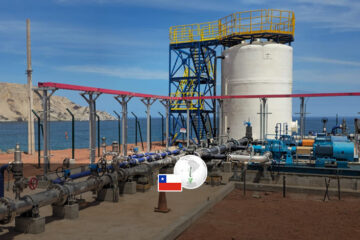
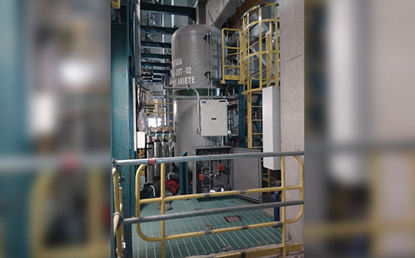
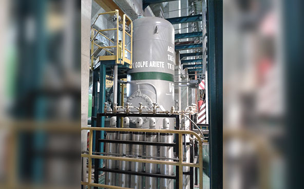
SUCCESSFUL CASE: Water Hammer Damping Station 4,000 Lts Pond

The main objective is to monitor and develop the replenishment of the Air/Water volumes inside the cylinder that makes up the water hammer dissipation station. For this it is necessary to know that, when the air is in direct contact with the water, it tends to dilute in the water, causing a loss of air volumetric capacity. Under this premise, an automatic control system is required to ensure the nominal condition, and to alert possible malfunctions to operations for their timely solution.
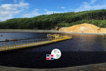
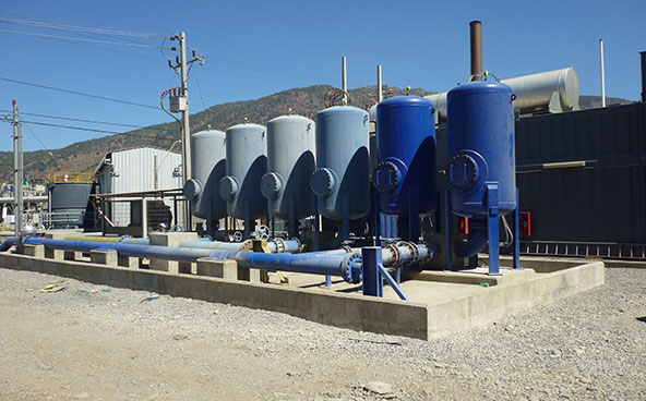
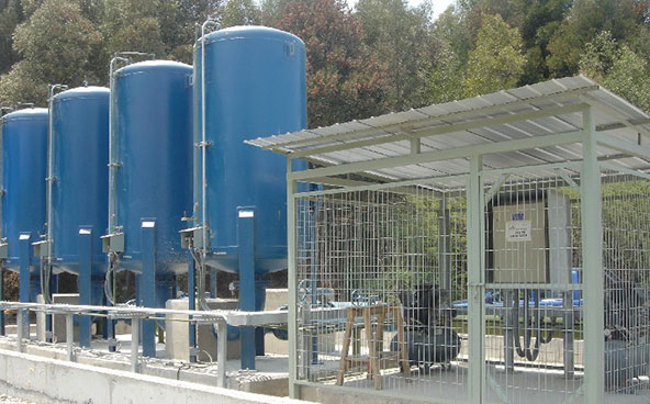
As it is a segmented station it is necessary to maintain a symmetry of levels inside the tanks, however, this symmetry has tolerances that allow a maximum imbalance before correcting such condition.
CONTROL LOGIC
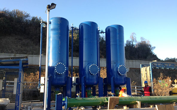
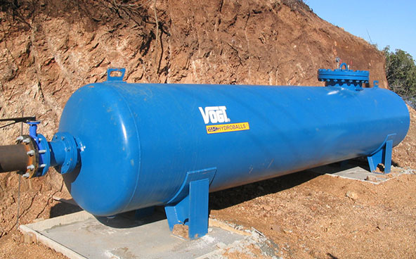
The installed water hammer damping tank has a capacity of 4m³. The water/air ratio that the tank must have to effectively damp a hydraulic transient must be 1.2m³ of air and 2.8m³ of water, this corresponds to a water column of 70% of the total capacity of the tank.
A water column of 70% water and 30% air corresponds to the equilibrium condition of the system. If after a hydraulic transient the water level varies above 80%, the program commands the air injection solenoid valve to inject air into the pond through the compressor air line to lower the water column back to the system equilibrium level (70%).
If a decrease in the water column with a level of less than 40% is generated, the system controller gives the order to discharge air from the pond through the discharge solenoid valve, causing the water column to return to the equilibrium level (70%) by means of the vacuum generated by discharging air from the pond.
The actuation of the air injection and discharge valves is generated by level alarms configured in the program installed in the controller.
The high and low level alarm levels are responsible for sending the opening signal for the air injection and discharge valves of the tank. The tolerance of these alarms is ±10% and can be adjusted through the operator panel to delay the level control action.

EAGA'S RELATIONSHIP WITH THE CONTROL ROOM
The water hammer damping station control system maintains communication with the control room by means of a 5-second (approx.) electronic flank change pulse. This pulse indicates to the central system that the damping station is "live".


TELEMETRY SYSTEM

PLC
The assembly basically consists of a Programmable Logic Controller (PLC) that governs the application according to the operational conditions defined by the associated field instrumentation and the operating ranges (set point) related to the pond water column level defined by the user.
Level Sensor
The reading is obtained through a capacitive type reference probe in contact with the water column inside the pond. The sensor output signal is of normalized type (4-20mA) and has a programming panel where the level calibration parameters can be adjusted by adjusting the capacitance (in pico farads).
The process variable measured in the level sensor instrument is translated into an electrical signal of standard characteristic (4-20mA), entered to the controller which, according to the programmed control routines, determines the opening or closing of the bleed or air injection valves of the line that connects the compressor with the tank, as appropriate.
HMI
It shows in real time the levels of each tank and its hydraulic distribution, the application has a manual and automatic operation, so that if there is no local intervention in a period of 5 minutes, the system is switched to automatic mode, in order to ensure its normal operation.
Compressor
It has a connection block that incorporates a pressure preso-switch and thermal protection for the motor, that is to say, the unit is autonomous in its accumulation capacity and supplies air to the tank as the process requires it, this finally determines that from the view panel the power supply of the equipment is determined and the compressor operation time record is obtained.
If you want to know more click here: https://www.vogt.cl/estanques/