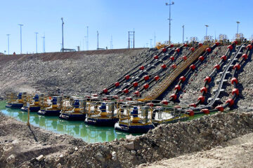
A water hammer damping station must maintain defined operating conditions to respond appropriately to hydraulic transients in a pressurized water system.
In this project, we developed the automation and control system for a 4m³ hydropneumatic tank, incorporating instrumentation, automatic valves, a PLC, an HMI, and communication with the control room.
The main objective was to monitor and regulate the volumes of water and air within the tank, maintaining its nominal operating condition and generating alerts in the event of possible deviations.
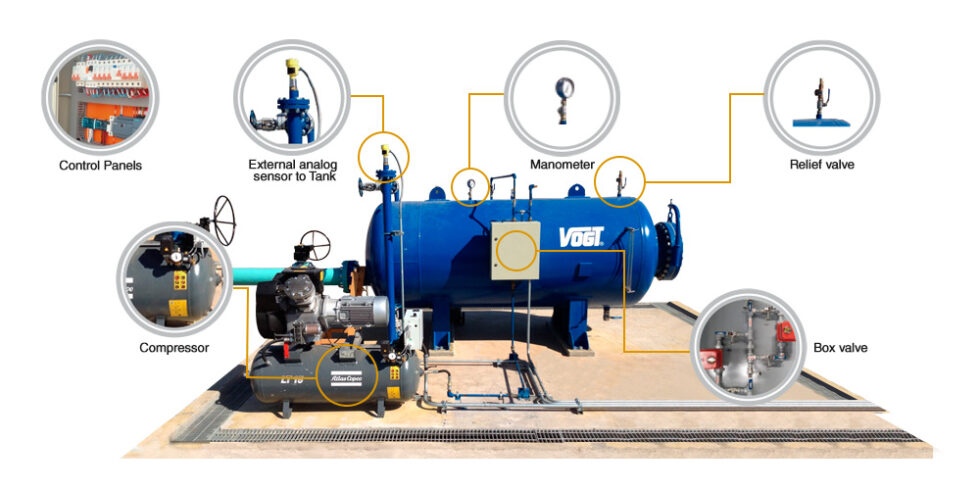
The Challenge: Maintaining the Water-to-Air Ratio
In this type of tank, the air is in direct contact with the water and can gradually dissolve into it. This loss of air volume alters the tank’s internal ratio and can affect its ability to dampen a hydraulic transient.
The equilibrium condition defined for the equipment was:
- 2.8m³ of water, equivalent to 70% of its capacity.
- 1.2m³ of air, equivalent to the remaining 30%.
Because the station was segmented, it was also necessary to maintain a balanced distribution among the tanks, taking operational tolerances into account before performing an automatic correction.
Automatic Level Control
To maintain the nominal water-to-air ratio, we implemented a control logic based on continuous measurement of the level inside the tank.
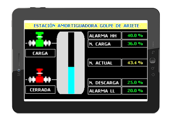
When the water column exceeds 80% of capacity, the system commands the opening of an injection solenoid valve. The compressor supplies air to the tank, displacing the water until the 70% equilibrium level is restored.
When the water level drops below 40%, the controller activates the air discharge solenoid valve. This action allows water to re-enter until the nominal condition is restored.
The high- and low-level alarms have an adjustable tolerance of ±10%, which can be configured from the control panel according to system requirements.
Station Instrumentation and Automation
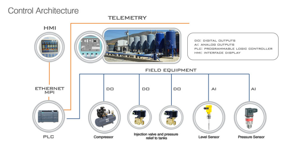
The solution integrated various components to monitor and control operations:
• Programmable Logic Controller
The PLC processes signals from the field instrumentation and executes the configured control routines. Based on the measured level, it determines whether to open or close the air injection and discharge valves.
• Level sensor
The measurement is performed using a capacitive probe in contact with the water column. The instrument transmits a standardized 4–20 mA signal to the controller, allowing for continuous monitoring of the tank level.
• HMI Interface
The interface displays tank levels and their hydraulic distribution in real time. The system allows operation in either manual or automatic mode.
If there is no local intervention for five minutes, the application automatically switches to automatic mode to maintain normal station operation.
• Compressed Air System
The compressor features pressure control and thermal protection for the motor. Its function is to supply air to the tank when the process requires it.
From the control panel, it is also possible to control its power supply and record the cumulative operating time.
• Communication with the control room
The station maintains communication with the central system via a periodic electronic pulse lasting approximately five seconds.
This signal allows the control room to confirm that the buffer station is operational and that its automation system maintains active communication.
A Solution Focused on Operational Continuity
Automation enables the system to maintain the water-to-air ratio required for the reservoir’s operation, correct deviations, and provide timely alerts when conditions fall outside established ranges.
This project integrated hydraulic engineering, instrumentation, control, and communication to improve the monitoring of a water hammer damping station and contribute to the reliable operation of the pressure system.
Do you need to protect a pressure line against water hammer?
Learn about our hydropneumatic tank solutions and their main applications.